Internal Combustion Engines
Introduction
Indeed, the engine industries have seen a tremendous growth in the research and development of new-age technologies over the past ten years or so. Even though a huge database is now available on present-day engine technologies, a skillful presentation of those data is a demanding task.
Internal combustion engines are divided into two main categories: spark ignition and compression ignition engines. In spark ignition engines, the working fluid is the mixture of fuel with high octane number and air, while in compression ignition engines, the working fluid is high cetane number fuel, which is added to the cylinder in a controlled direct injection after air entry and gradual reduction of cylinder volume. The reason for the widespread use of internal combustion engines in the land, air and sea transportation industry and power plants is their simplicity, high power and high power density.
Another factor influencing the development process of internal combustion engines is their consumption. Gasoline and lighter fuels, such as crude oil derivatives, were created in carburetors to evaporate fuel and provide a more homogeneous air-fuel mixture.
During the last three decades, new determining factors were considered to affect the design and production stages of the engine such as:
-
Engine pollution control
-
Fuel consumption
-
Engine power increase
A set of research activities performed in the field of internal combustion engines
This set of activities includes experimental and numerical studies, which are briefly mentioned below.
Conversion of mechanical injector to electronical injector and common rail fuel system
The mechanical injector (four-hole) in a single-cylinder compression-ignition engine (Daedong with a maximum power of 11 hp) was replaced with a common rail fuel injection system with an electric injector (eight-hole) in the internal combustion engine laboratory of Noshirvani University of Technology. The engine’s performance has been investigated and compared experimentally with both of these injectors. For purpose, the performance of the electric injector was analyzed at two different injection start times. Initially, the injection control system was designed for the electrical solenoid rail injector system and direct control capability.
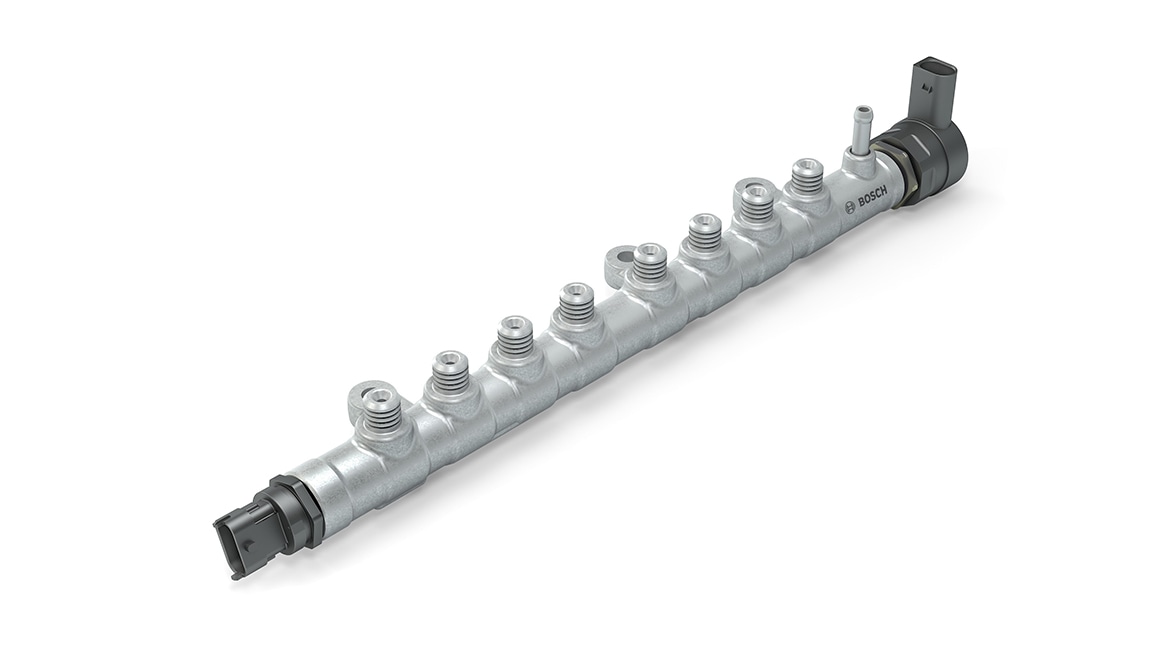
Figure 1: common rail and barometer for measuring the pressure inside the rail
Fuel injection into the combustion chamber has been evaluated in terms of injection pressure, injection time and injection start time. After that, engine performance in combustion characteristics and emission aspects were investigated. These tests were performed at a constant speed of 1150 rpm, idle and in low-load operation with a braking power of 1.22 kW on the engine. Using the pressure data obtained from the experiments, the rate of heat release, total energy released, combustion start, combustion delay, combustion duration, combustion efficiency and fuel conversion efficiency have been studied.
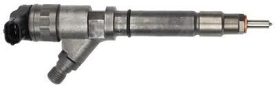
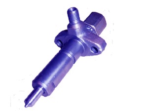
Figure 2 : solenoid injector Figure 3 : mechanical injector
Fuel circuit performance check and Taking full control of the fuel injection process
Investigation of diesel engine fuel circuit performance and the effect of fuel injection duration and magnitude of fuel injection pressure inside the combustion chamber to reduce engine pollution and noise, as well as further improvement of power and engine efficiency were done. For this purpose, in this institute, experimental methods and numerical simulation methods with three-dimensional and one-dimensional specialized softwares in the form of fluids and thermodynamics are studied.
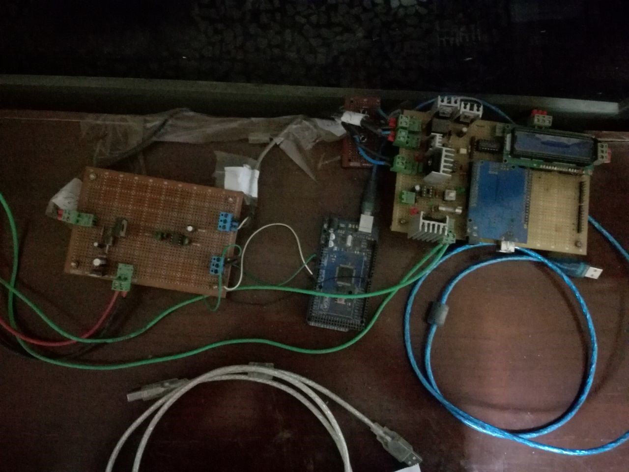
Figure 4 : Circuits and engine control system
Investigating the use of renewable energy sources in internal combustion engines
In this laboratory, extensive studies have been carried out on the use of various types of biodiesel fuels in different mass ratios combined with diesel fuel.
Types of waste oils were mixed additively with different volume percentages including B5, B10, B20 with diesel fuel and its effect on the performance and pollution of the combustion engine was investigated.
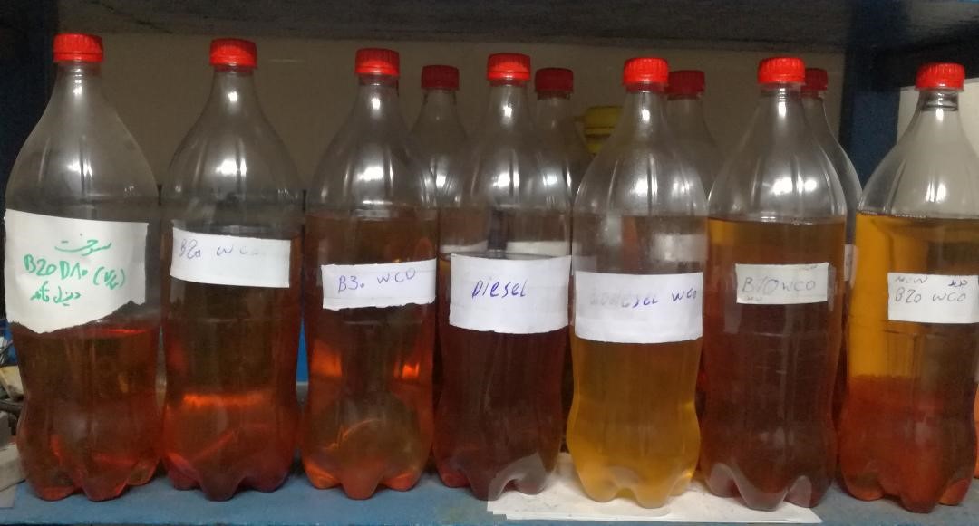
Figure 5: Combined diesel and biodiesel fuels prepared with different percentages
Add low reactivity fuel nozzle
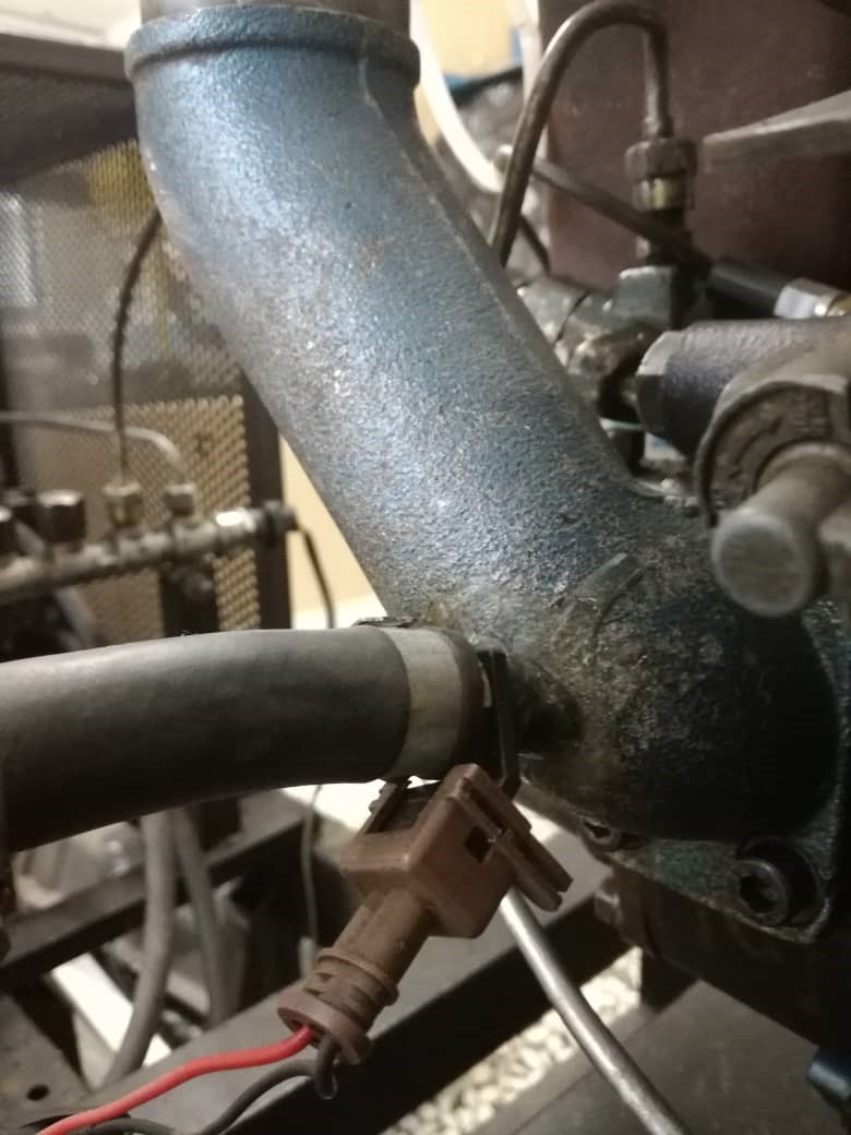
Figure 6: Addition of LRF fuel injector
Engine specifications are shown in Table 1. In this engine, a common rail system is used to inject fuel into the combustion chamber and a port injection tool (as a point injection) is used. Gasoline fuel, after being sprayed on the port, enters the cylinder mixed with air, and diesel fuel is injected directly into the combustion chamber. The specifications of the fuel injector are also shown in Table 2. The mass of diesel fuel injected per cycle is equal to 10.5 mg and the mass of gasoline fuel injected per cycle is equal to 5 mg.
Table 1. Engine specifications Table 2. Injector specifications
|
Port injection system |
Common rail system |
parameter |
|
5 |
8 |
Hole No. |
|
- |
120 |
Hole Bore (µm) |
|
specifications |
parameter |
|
Daedong 11 Hp,1_cylinder |
motor |
|
92 |
Bore (mm) |
|
95 |
Stroke(mm) |
|
630 |
Displacement volume(cc) |
|
17 |
Compression Ratio |
|
20 |
IVO (CAD bTDC) |
|
47 |
IVC (CAD bTDC) |
|
35 |
EVO (CAD bTDC) |
|
14 |
EVC (CAD bTDC) |
Experimental study of fuel injections different characteristics effect
Fuel atomization, fuel-air mixture homogenization, penetration of fuel in compressed air inside the cylinder are the factors that cause a perfect combustion in the engine, which is done in this laboratory by changing the mechanical injector to electronic injector and producing high pressure, done to have more fuel atomization and more fuel penetration in the compressed air of the cylinder, resulting in more homogenization of the fuel-air mixture inside the engine. The effects of these fuel characteristics results in more power, less pollution and reduced shocks inside the cylinder which were subsequently studied and developed.
Injection pressure (rail pressure control)
There are several ways to control fuel injection pressure. Common rail fuel systems are equipped with a closed-loop high pressure control system that stabilizes the rail pressure at a relatively small margin to the nominal value set by the electronic control unit for specific engine operating conditions.
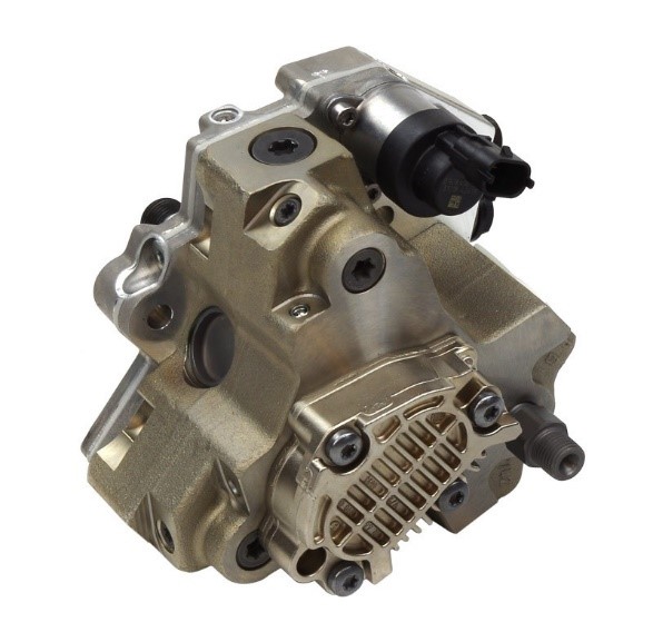
Figure 7: High pressure pump and pressure control valve in the inlet path
Fuel injection start
Related to reaching low engine temperature (PCCI, RCCI) and increasing the level of fuel-air mixtures homogenization.
Fuel injection duration
Fuel inlet mass control as well as adjusting the fuel penetration at a specified rail pressure, to prevent the accumulation of fuel points and increase the level of homogenization.
Convert simple diesel engine to RCCI engine
Simultaneous injection strategy of high octane fuel and high cetane fuel, gasoline and diesel, and early fuel injection to achieve low temperature combustion mode.
Investigation of different modes of low temperature combustion (PCCI & RCCI)
Fuel injection start change and early fuel injection in the presence or absence of inlet air containing high octane fuel.
Adding additive
After implementing low temperature conditions in RCCI mode, using two fuels: diesel (direct injection fuel) and gasoline (fuel mixed with inlet air) to further improve combustion conditions, reduce pollution and increase power, ethanol 96% fuel as a fuel mixed with mixture of air and gasoline fuel was used in RCCI mode and different ratios of gasoline and ethanol, in constant equivalence ratios were examined.
One-dimentional simulation (Cooling system and heat recovery system and High pressure fuel supply system of common rail, steps of engine output efficiency increase)
In order to predict and feasibility of converting the engine in the laboratory into a marine engine model with a conventional cooling system used in the marine transport system, an attempt was made to simulate a one-dimensional model of the engine in GTSUIT software. During this process, the fuel supply circuit was completely and accurately simulated to use this model if necessary to adopt control characteristics and ease of calculations to determine the pressure and spray interval required to achieve the appropriate fuel mass in each cycle.
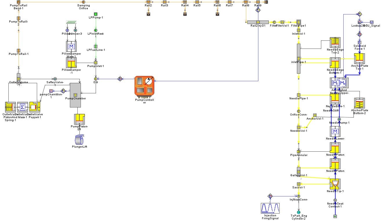
Figure 8: injector and common rail fuel supply circuit simulated in GT-SUITE software
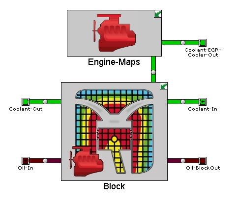
Figure 9: Engine cooling circuit simulated in GT-SUITE software
Three-Dimentional simulation
In this simulation, AVL fire 2014 software is used as a coupling with Chemical joint kinetics related to isoctane-nheptane combined fuel, including 77 species and 473 reactions. The schematic view of the simultaneous operation of the software with the chemical joint kinetic code can be seen in Figure 10.
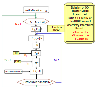
Figure 10: Chemkin and AVL Fire coupling flowchart
To conduct this research, the geometry of the empty volume of the engine combustion chamber was modeled and plotted while the piston was at the TDC, and in order to prepare the CFD calculations, a structure mesh was formed on the geometry.
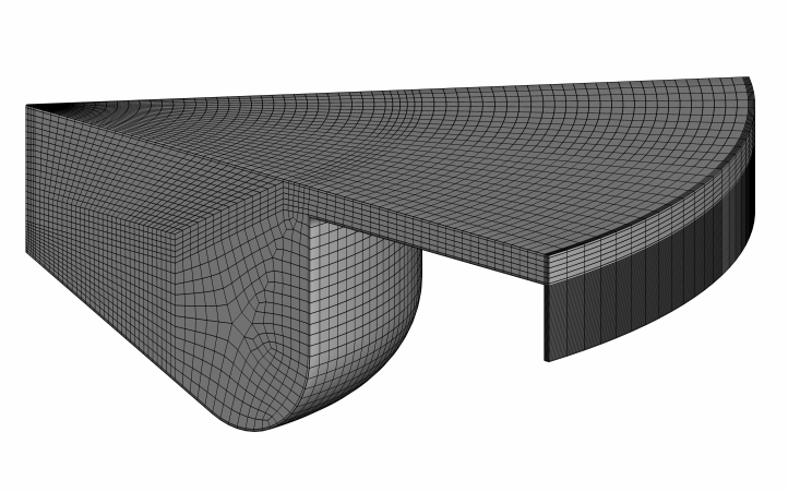
Figure 11: Meshing at TDC
It is noteworthy that the geometry of the engine is symmetrically divided into completely similar parts based on the number of nozzle holes, so that the number of cells in the computational network is reduced and the computational speed is increased; Therefore, considering that the engine nozzle has 8 holes, one-eighth of the engine geometry has been simulated.
Investigating the effect of fuel injection moment and duration
Accurate study of computational fluid dynamics to analyze the phenomena inside the combustion chamber as well as the amount of fuel penetration, investigate the effect of pressure and fuel injection duration and finding a range to prevent fuel accumulation in the piston bowl, as well as finding limits of fuel injection start moment changes and to prevent fuel from hitting the edge of the piston bowl.
additive
Investigating the possibility of controlling the outlet air temperature and the feasibility of reducing fuel consumption with the help of computational and numerical fluid dynamics studies of the effect of water spraying in the engine combustion chamber in RCCI mode by direct water spraying and adding water to the inlet fuel-air mixture and finding existing constraints to implement the proposed idea.